Building an Amateur Television Yagi Antenna

At W1HLO, we have been experimenting with the broadcast of amateur television (ATV) for one of our projects. The use of fast-scan television can provide a wide range of projects for our students to work on. Students can produce their own shows (either live or pre-recorded), learn how television broadcasts are transmitted and received, and build antennas to receive the broadcasts at home. ATV can also be a relatively cheap amateur endeavor by sticking with analog, standard definition (SD) television. Older analog TVs can be found for free, along with SD studio cameras for cheap or free. To transmit an ATV SD signal, a low-costing transmitter like the MFJ-8709 can be used and transmit up to 4W using a CPU heatsink and fan strapped to its back. (I don't recommend the lower-powered MFJ-8704 as we've had issues with them consistently working correctly.)
To receive our broadcasts at home and to have our students try to receive other TV broadcasts, we built yagi antennas centered on 441MHz. (We broadcast on cable channel 59 over the air from our shack, and 411MHz is the center frequency.) Yagi antennas are a very forgiving antenna to construct and are an easy hands-on project to build. This kind of antenna is directional, and allows students to move the yagi antenna around in the air to see where the TV signal is coming from.
There are plenty of plans out there to make yagi antennas out of metal tape measures, however, I like to work with solid copper wire. For this project, we used 6 AWG solid bare wire (which is 4.11mm in diameter). The boom was cut from a piece of 1/2" x 1" wood in 55cm lengths. Quick Yagi 4 was used along with DOSBox to model the antenna and calculate the lenths of the elements. (Yes, I know there are more modern yagi modeling software applications out there, however, Quick Yagi 4 is relatively easy to use and a manual is not needed to figure it out!) An antenna with three driven elements was designed with a forward gain of around 9dB. Below is a table of the element spacing and sizes and a radiation map.
| Element Name | Spacing from Driven | Element Length |
|---|---|---|
| Reflector | 8cm | 34cm |
| Driven | 33cm | |
| Director 1 (D1) | 7cm | 31cm |
| Director 2 (D2) | 10cm | 28cm |
| Director 3 (D3) | 14cm | 27cm |
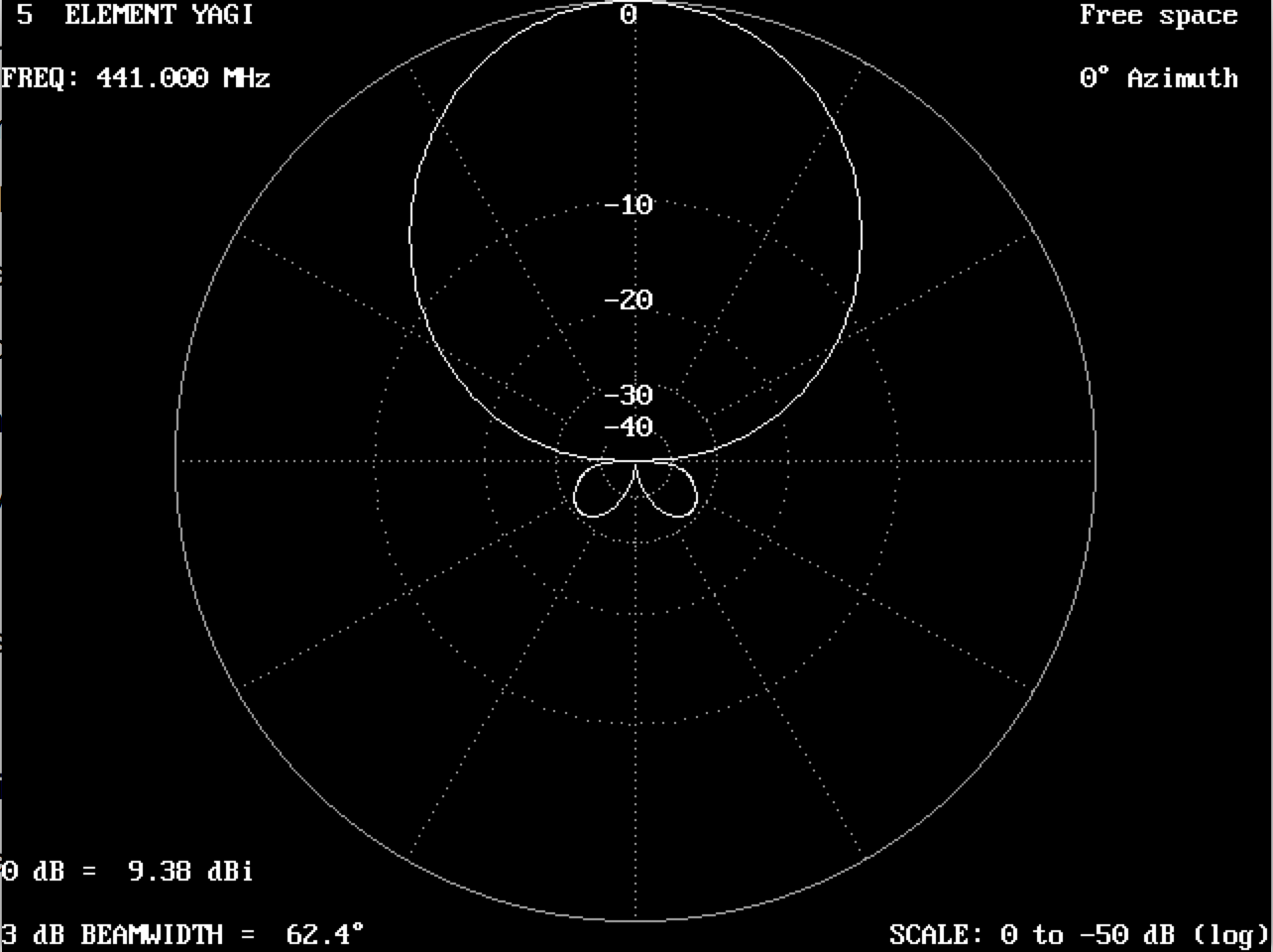
Using the table above, students cut the 6AWG wire into lengths for the reflector and three driven elements. Holes were drilled into the wooden boom using the spacings in the table and the elements were hot glued into place. A folded dipole was used as the driven. To create the 33cm-wide folded dipole, a jig was made by designing guides in Autodesk's Fusion 360 and 3D printed. The guides were mounted to a piece of wood with drywall screws. Students then bent a 74cm piece of wire into the folded dipole using the jig. You can download the parts to 3D print them yourself from Thingiverse.
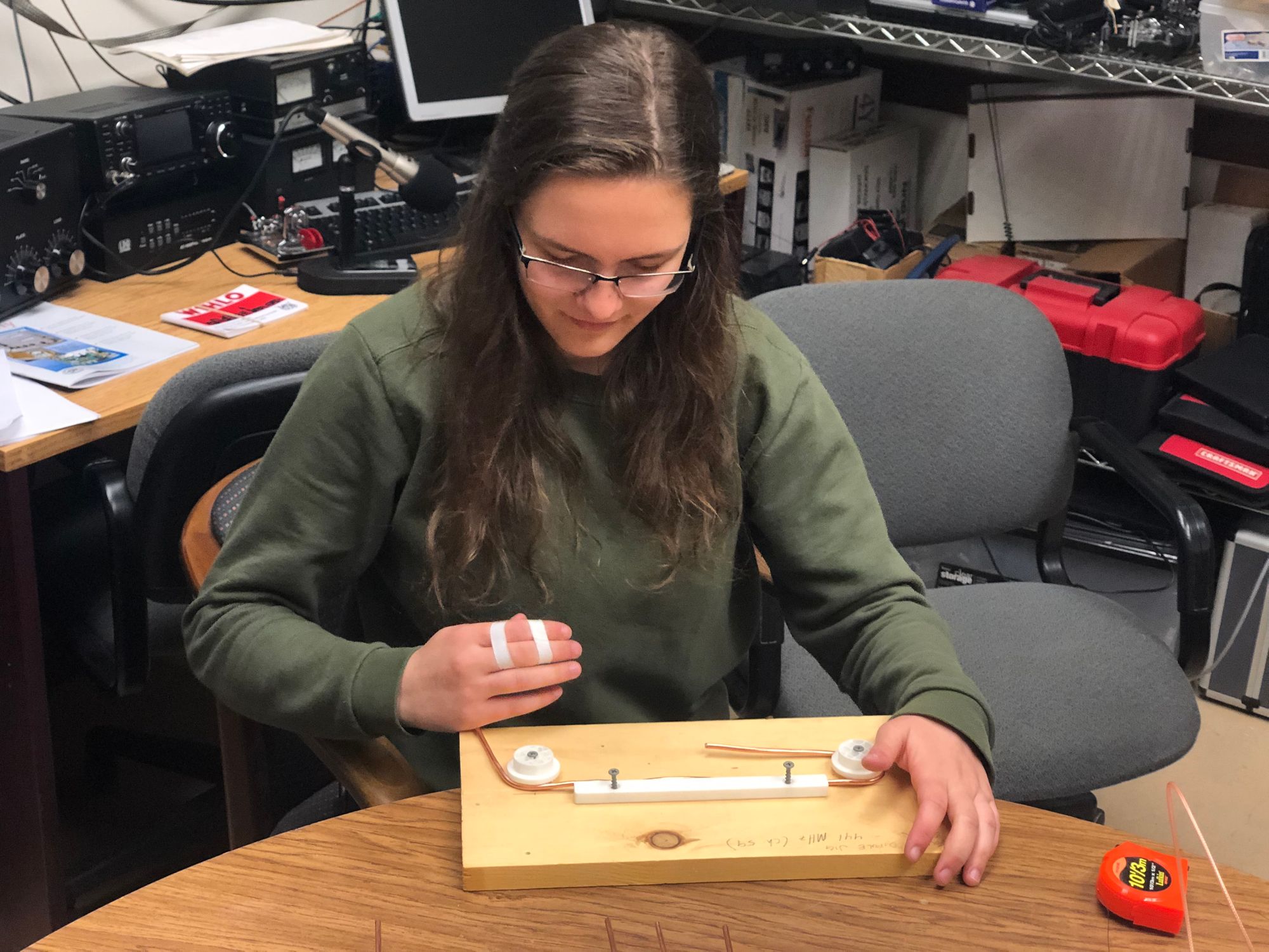
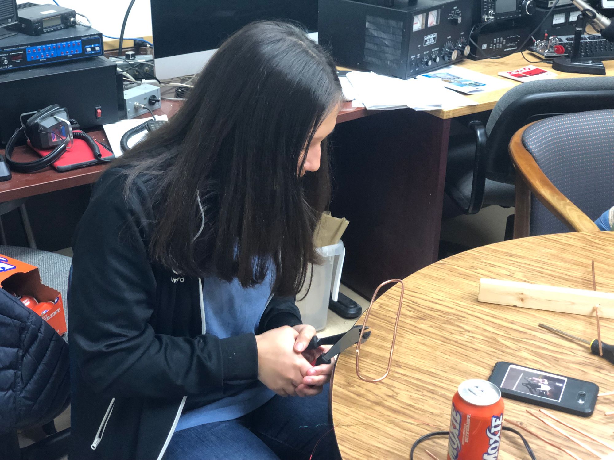
After the folded dipole was bent, it was trimmed so that the feedpoint was about a 1cm gap.
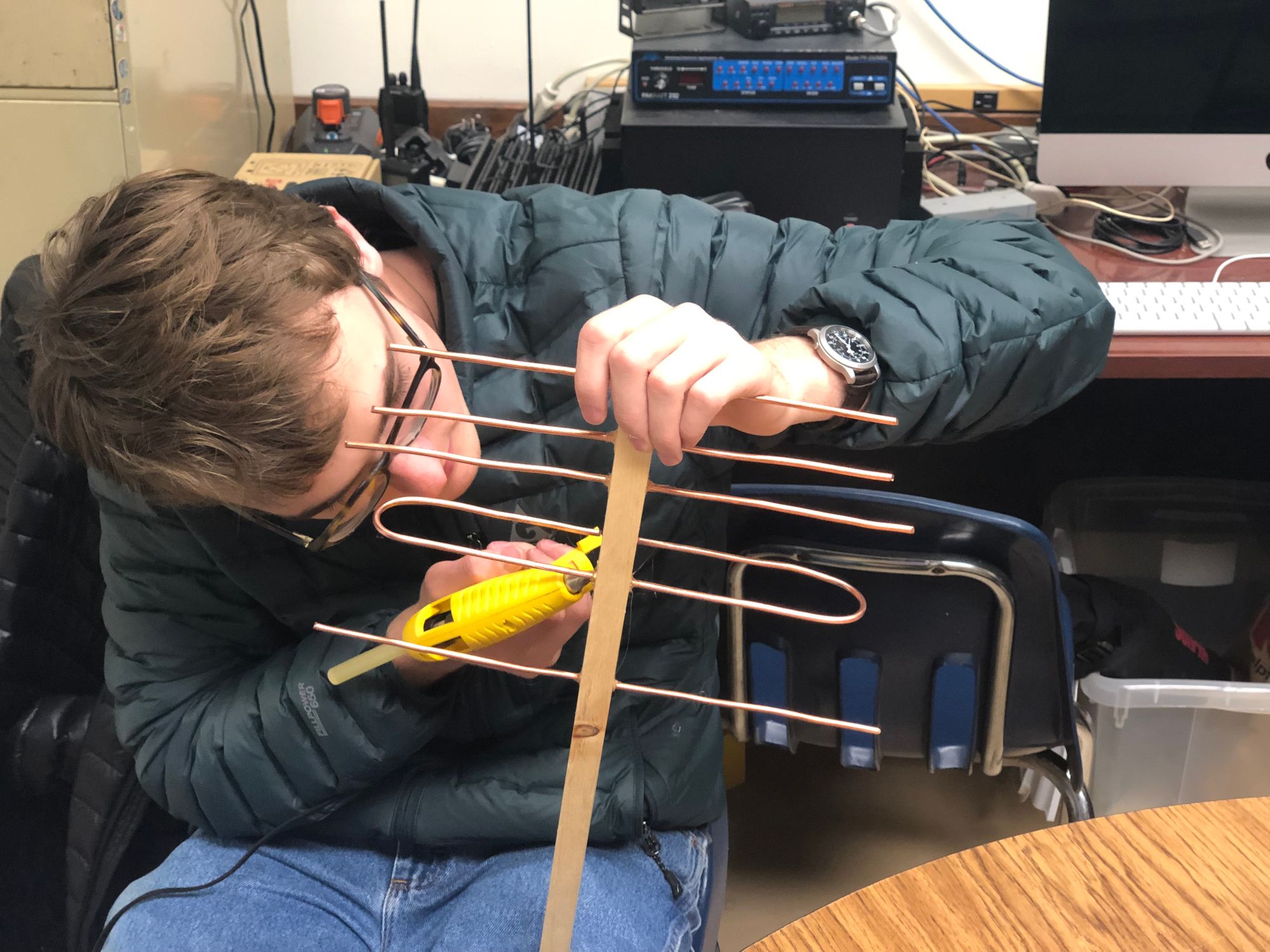
Then, the folded dipole was hot glued into the yagi's boom.
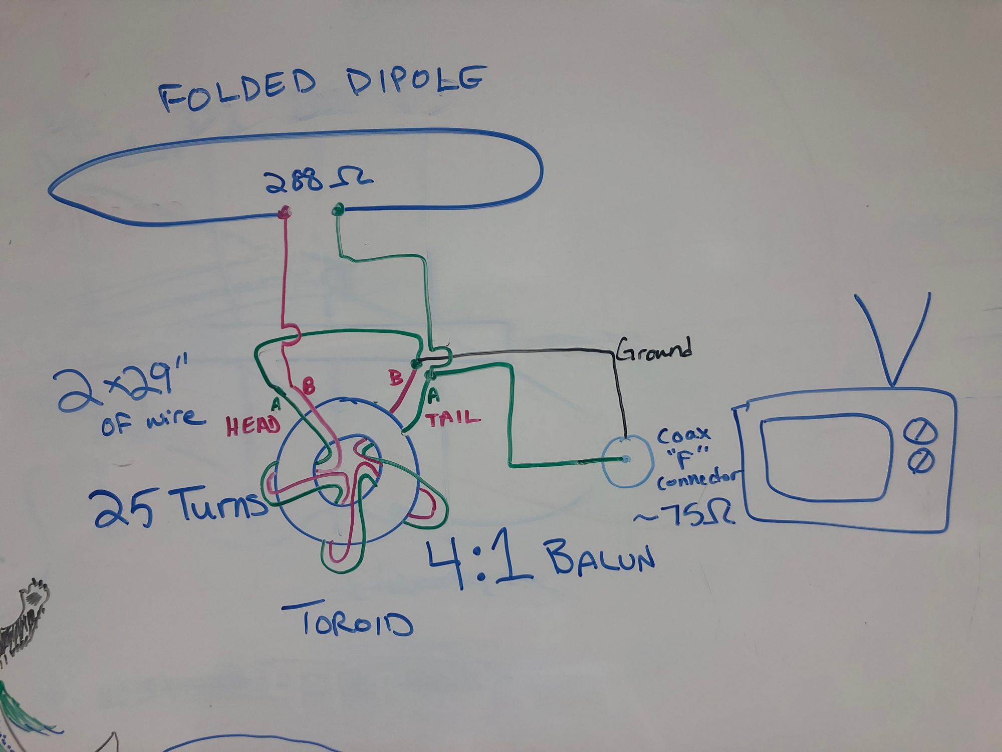
As the feedpoint impedance for a folded dipole is always around 288 Ohms, and we want to connect the antenna to the 75 Ohm input of a TV, we needed to divide the feedpoint impedance by four. To do so, we wound a 4:1 balun using the instructions from RASON (check out RASON's other projects – we are so fortunate to have a local amateur radio club that hosts awesome information on their website!) We ordered a dozen T80-2 toroid cores from eBay and tracked down some 26AWG red-colored and green-colored enameled magnet wire. We then wound the toroid 25 times with a pair of 29" wires and soldered the appropriate wires to the folded dipole's feedpoint and an F connector.

Now our 441MHz yagis are ready to pick up some ATV signals! 73!
